SQL Tutorial Course from Craig Dickson
Designing a Relational Database and Creating an Entity Relationship Diagram
Learn to create, update and interrogate your own fully-functional relational database using SQL with free open-source software — Part 1
![]()
This is part 1 of a 3-part series taking you through the process of designing, coding, implementing and querying a relational database, starting from zero. See part 2 (Coding and Implementing a Relational Database using MySQL) here , and part 3 (Data Analysis in MySQL — Operators, Joins and More in Relational Databases) here .
All the code and information for this tutorial can be found on the associated GitHub repository . I used Lucidchart to make the diagrams shown in the article.
When I first started using databases at work and writing SQL queries, I was always slightly terrified that I would accidentally delete all of the production data that my company relies on. As a result, I was very tentative about which queries I made and what I did. Over time, I learned more about how to use and interact with databases using some different flavours of Structured Query Language (SQL to its friends).
In this series of articles, I'm going to share what I've learned and go through the process of creating a Relational Database using MySQL (and MySQL Server) from the very beginning, and hopefully clarify things enough on the way that you can get started building your own and feel confident that you won't accidentally delete all the data!
We're first going to look at what exactly a Relational Database is and how it works, and then walk through the process of building one, from thinking about what we want the database to do (or receiving requirements from colleagues or clients explaining what they would like it to do), to planning the tables and their relations, to writing the SQL code to create and populate the database itself. Then at the end we will have some fun writing queries!
What is a Relational Database?
According to Oracle, a relational database is "a type of database that stores and provides access to data points that are related to one another". OK, sounds good!
We can create, read, update and delete (the basic functions of any database) the information in our relational database using a Relational Database Management System (RDBMS). Example of RDBMSs include Oracle, Microsoft SQl Server, MySQL, and PostgreSQL, among many others. Each of these have their pros and cons (and like everything coding-adjacent, their online hyper-partisans), and SQL is not implemented in exactly the same way in each of them. The concepts are the same, but the syntax and keywords may be slightly different, so it is not usually possible to use SQL code written for PostgreSQL in Microsoft SQL Server, for example, without making some modifications.
We will be using MySQL Community Server because it's free, powerful and open-source, but the others are all good choices too.
Within a relational database, records are stored in tables (think Excel spreadsheets, if that's something you're familiar with) where each column is an attribute (e.g product name, purchase cost, retail price) and each row represents a record (a particular item or instance which has those attributes).
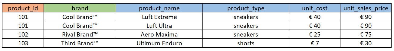
In this very simple example for a store, 'product_id', 'brand', 'product_name', 'unit_cost' and 'unit_sales_price' are all attributes, and each row is a record for a particular product ('Cool Brand™ Luft Extreme Sneakers', 'Rival Brand™ Aero Maxima Sneakers', etc) .
Primary key
Each product here has a 'product_id' field, coloured red in the image above. This is what's called the 'Primary Key'. Every record in every table in your database has to have an attribute (or combination of attributes) which identifies it uniquely — this is known as the primary key.
In our case, an arbitrary 'product_id' has been assigned to each record. It would also be possible to use a 'composite key' made up of, for example, the 'product_name' and 'product_type' attributes together, presuming that these identify a product uniquely (i.e. that Cool Brand™ etc never release another product with the same name). Which to use depends on the nature of your data — what is important is that every table has a primary key, it must be unique and it cannot be NULL.
What makes a relational database relational is, you might not be surprised to learn, the relations between the data stored in the tables. For example, connected to our product table above, we may have a further table with all the details of all the brands that are sold in our store.

Now we have two tables, each for a particular entity — the products sold in our store, and the brands who produce them. In our brand table, the brand name is the primary key — the unique identifier for each record.
Foreign key
We can express the relationship between these entities (in this case, that the brand is the producer of the product) by including the primary key from the brand database as a 'foreign key' in the products database. This means that each product can be associated with the appropriate brand in our database.
This is very useful as it means these tables are connected in a meaningful way and we can easily find the name of the contact person responsible for the 'Luft Extreme Sneakers', for example. We will look at how exactly this is done using SQL code later in this series.
In our example, we can make the brand attribute on our products table work as the foreign key which stores the relationship between these two tables.
In this case it is possible (in fact it is very likely) that each brand will have multiple products associated with it. It is also likely that each product is associated with one and only one brand (we'll ignore the existence of cross-brand collaborations here). This means we have a 1-to-N relationship between these entities — a brand may have N products associated with it (N just meaning any number), a product may have 1 brand associated with it.
This attribute of the relationship, how many other entities an entity can have a relationship with, is known as the cardinality of the relationship. Other relationships include 1-to-1 and N-to-M (many to many). We will discuss these later.
As each product can have one and only one brand, it makes perfect sense to store the unique identifier of that brand (in our example, the brand name) as an attribute of that product. This means when we want to find information stored on the brand table relating to a particular product, we can easily use the value of the brand column (Cool Brand™, Rival Brand™, etc) to 'look up' the relevant information on the brand table.
It is in this way that the brand column on the product table can be said to work as the 'key' which unlocks the information in the other ('foreign') table.
If we tried to store the key for the product on the brand table, we'd have to have a record for each product — making the separation of the data pointless and creating unnecessary redundancy in our database. This is the reason that we store the foreign key on the table which is on the N side of a 1-to-N relationship.
Our database can become very complex as we start having multiple tables with different relationships to one another, but the fundamentals to focus on here are:
- Each table has a primary key which uniquely identifies each record in the table, and which cannot be null.
- For each relationship table A has to another table, it requires a foreign key as an attribute in table A to define that relationship.
This is how we define the relations between the data in a 1-to-N relationship in a relational database.
Designing a Database
As always, it will help us to walk through a real-life example here. Let's design a database based on our own requirements!
Defining the requirements
The first thing to think about when creating a database is what we want it for. This may seem obvious, but is worth stating explicitly. Different requirements will lead to different information structures, relationships, designs and implementations.
It's also important to note that the same requirements can be successfully met through different designs and implementations, and it's not always true that there is one best implementation to solve a particular problem. There are definitely solutions which are better and worse than others, but I'll leave those arguments to threads on Stack Overflow!
So what is our use case? We are going to create a relatively simple database for a language school based in Berlin, Germany. I have worked as a teacher of English as a Foreign Language in Berlin for some time, so this is an example which is near to my heart. And you know what they say, write what you know .
It's a good idea to write down your requirements, or if you're working for a client or creating a database for use by another department in your company, get the requirements in written form from the end users of the database.
What information do they want to store? What types of entities do we need to create tables for (customers, orders, products, courses, website-clicks, data downloads, etc)? As with anything to do with taking advantage of data, to make our work most effective we need to think about what the use cases are and what our users are looking for.
Here are the requirements for our example database:
The International Language School is a language training school.
It offers language classes for corporate clients, which can be conducted at the School or at the offices of the client as they prefer. The School employs teachers, each of whom may teach multiple courses.
The school has clients, each of whom may offer multiple courses via the school. Clients offer courses to their employees, who have the option to participate.
Each course is offered by one client. Each course has one teacher at any given time.
Participants in the courses are employees of the client companies, i.e. they work for the client companies. Each participant can be employed by one company at a time. Participants may be enrolled in more than one course.
Bear in mind that a real requirements document will likely be longer and more complex than this, but this one will give us the information we need to build our example database.
Making a plan based on the requirements
The first thing to do is to read the requirements document carefully, making note of the things which might become entities in our database, and the possible relationships between them.
It is important at this stage to ask questions to clarify the requirements. It's natural for people who work with something every day to think of some things as 'common sense' or obvious, when they may not be obvious to someone coming from outside that area of work. Also, people might sometimes not be used to thinking about these aspects of their work with the rigour necessary to create a database.
This is where our soft skills come in, and the ability to facilitate clear communication between technical and less-technical employees is most valuable. We really don't want to spend a lot of time designing, coding and implementing a huge database only to find that we had assumed each participant could only take one course, when in fact they can take multiple course, for example. Planning is important!
A very useful intermediate step between getting the requirements and implementing our database in SQL is creating an Entity Relationship Diagram (ERD). This is, as you might anticipate, a diagram which maps the relationships between the entities that we will build into our database. The process of putting this diagram together can help us straighten out the relationships and identify important insights or redundant attributes as we go.
Some people might skip this step and go straight to coding, but creating an ERD to make sure we have everything planned out before we build the database itself is best practice, and strongly recommended.
Identifying the entities
Let's go through the requirements and see if we can identify our entities. These will most often be people, things, events or locations.
Just looking at the first paragraph of our requirements document we can see clients, office locations, teachers, and courses as possible entities for our database. The rest of the document gives us various pieces of information about the relationships between these entities, and also mentions participants (employees of the clients, but from the point of view of the school, these are participants in the language courses).
So we have as candidate entities:
- clients
- office locations
- teachers
- courses
- participants
These are all important and we will have to handle each of these in our database. For the sake of this article I will make the simplifying assumption that each client has one office, and the courses take place there (if they don't take place at the school itself). In real life one client may have multiple offices, or they may have a large facility with multiple locations where different courses take place. We could easily handle this using an RDBMS, but for the sake of reducing complexity, we will assume each client has one location for their classes.
So that means the entities that we will create tables for are: clients, teachers, courses and participants. Good stuff!
Which attributes do we want to store?
Our next step is to think about which attributes we want to store for each of our entities. This may be spelled out in detail in our requirements document, or it may require more discretion on the part of the database developer.
Let's start with the teacher entity. We will want to store the name of the teacher, perhaps their date of birth, their contact information, tax or legal information, and — as this is a language school — the languages they teach. This might give us something like this to start with.
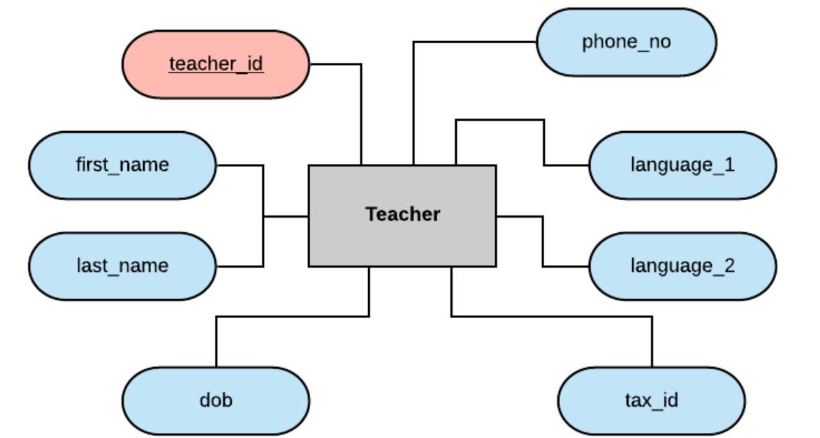
In a real-life situation we would probably store significantly more detail (for example the teacher's address, their starting date with the school, perhaps their payment rate for teaching, etc), but for our purposes this will be enough to work with.
Notice that we have created an arbitrary 'teacher_id' to use as our primary key here. We could have tried for a natural key using the combination of first_name and last_name, but what if our school employs two teachers with the same name in the future? Unlikely perhaps, but definitely not impossible. These are the kinds of things we need to consider during the planning stage.
We repeat the process for each entity, thinking about what information is relevant. During this process we will often discover that what we thought of as an attribute might be better represented as its own table, or we might notice that the same information is being stored reduntantly on two tables. These are the kinds of insights that are gained from creating an ERD as part of the database construction process, saving us time later in the process by surfacing possible problems early.
Let's do this for our remaining entities, beginning with the client entity.

Here we are storing the client_name, address and industry attributes, alongside a unique client_id.
Now for the course entity:
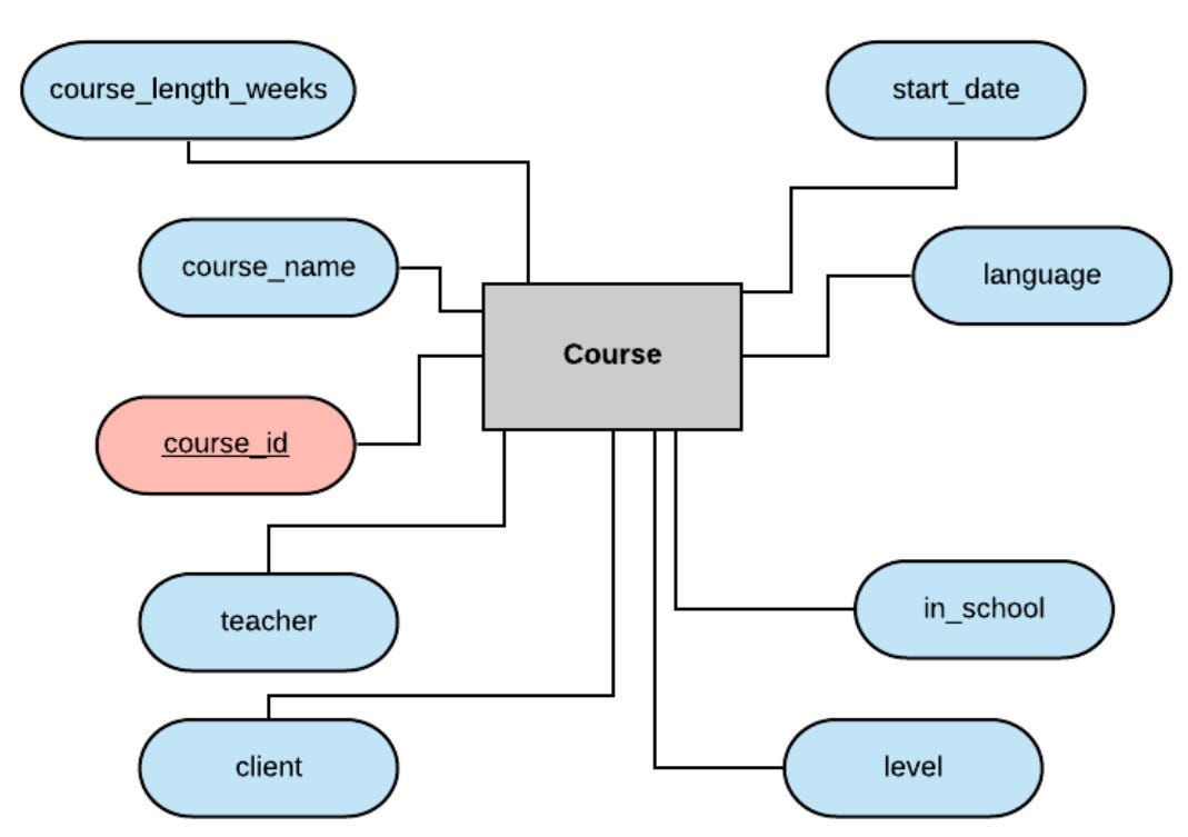
Here we are once again using course_id as an arbitrary primary key, alongside some very important attributes such as the course's name, its language and level, its start date and duration, the teacher of the course, the client, and if it takes place at the school or at the client's offices.
Now notice that we have a field for teacher and a field for client here. And we also have entities for teacher and client. This is where our relational database gets relational!
What we want to do is connect the entities (and the corresponding tables in our database) with each other, and we can do this using these attributes as our foreign keys. To understand this more clearly, let's take a look at the teacher course relationship in more detail.
Mapping the relationships
In our requirements document, it was stated that each course may have only one teacher at a time, which makes sense in this situation. It was also clarified that a teacher may teach multiple courses (this also makes sense, it would be hard for a teacher to pay the bills teaching just one lesson per week). So what we have here is a 1-to-N relationship!
We can model this in our ERD like so:
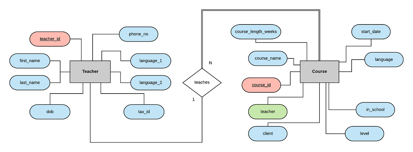
We connect these in our ERD through a relationship. This is often, but not always, modeled using a verb. In our case we can say that a teacher teaches a course, or — going the other way — a course is taught by a teacher. It makes sense to think of this relation as based on the verb 'teaches'. Notice that the 'teacher' field in our diagram is now coloured green, to remind us that this attribute is a foreign key, which references the teacher_id attribute in the teacher entity.
The single and double lines here refer to the participation level of the entity in the relationship. The double lines indicate total participation, which means every entity in the table must participate in the relationship — in our case this means every course must have a teacher. The single lines indicate partial participation, so in our case there may exist some teachers who are not yet or not currently teaching any courses. Here is a slightly longer explanation of this distinction if you would like to read some more.
We can do the same thing to model the relationship between client and course. Each client may offer multiple courses through the school, but each course may be associated with a maximum of 1 client, so again we have a 1-to-N relationship.
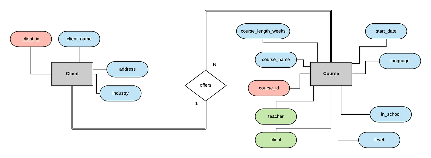
The entities on both sides of this relationship have double lines, indicating total participation on both sides of this relationship. This makes sense as the International Language School only offers classes on behalf of client companies, to those client's employees. It makes sense then that every course must be associated with one client, and every client must be associated with at least one course.
The final entity we want to model is our participants table, storing the participant's name, phone number, a participant_id as a primary key, and the name of the client which employs the participant:
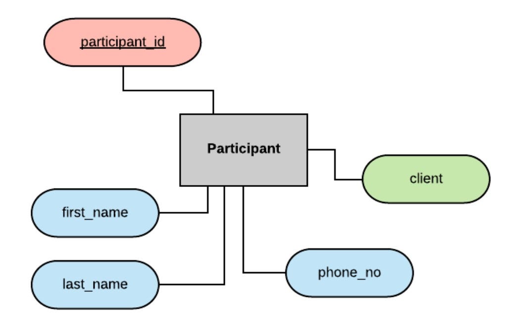
You can see that client is coloured green, and hopefully by this point you know why. If you said "because the client field is being used as a foreign key to store the relationship between clients and participants" then you win the prize! (The prize is the warm feeling you get from learning).
Once again, this is a 1-to-N relationship — clients may employ multiple participants, participants may only work for one client — and as each participant can work for one client only, the foreign key is stored on the participant table.
If we put all of this together, plus just a little more work (which we'll go through in a moment), we can create our final, complete, Entity Relationship Diagram:

Notice that the relationship between the Participant entity and the Course entity, here modeled as 'takes' (i.e. a participant takes a course, a course is taken by a participant), is a many-to-many, or N-to-M, relationship. An N-to-M relationship cannot be handled simply by use of foreign keys, but instead requires us to build a separate table in our database schema. We will go through this in detail in part 2.
In this article we have introduced the basic ideas of what a relational database is and how it works, discussed some of the different RDBMS packages available, and gone through the whole process of creating an Entity Relationship Diagram to describe the database we want to build based on the requirements document. That's a lot!
In the next part of this series, Coding and Implementing a Relational Database using MySQL, we will take things further and actually fully implement this database using MySQL Community Server. See you there!
Thanks very much for taking the time to come with me on this journey. I always welcome your feedback — please get in touch with me via my website and let me know how I could have done this more effectively! I am always open to constructive criticism, or any of your comments.
Until next time!

Source: https://towardsdatascience.com/designing-a-relational-database-and-creating-an-entity-relationship-diagram-89c1c19320b2
Posted by: annikaannikadyronowe0266595.blogspot.com


0 Comments